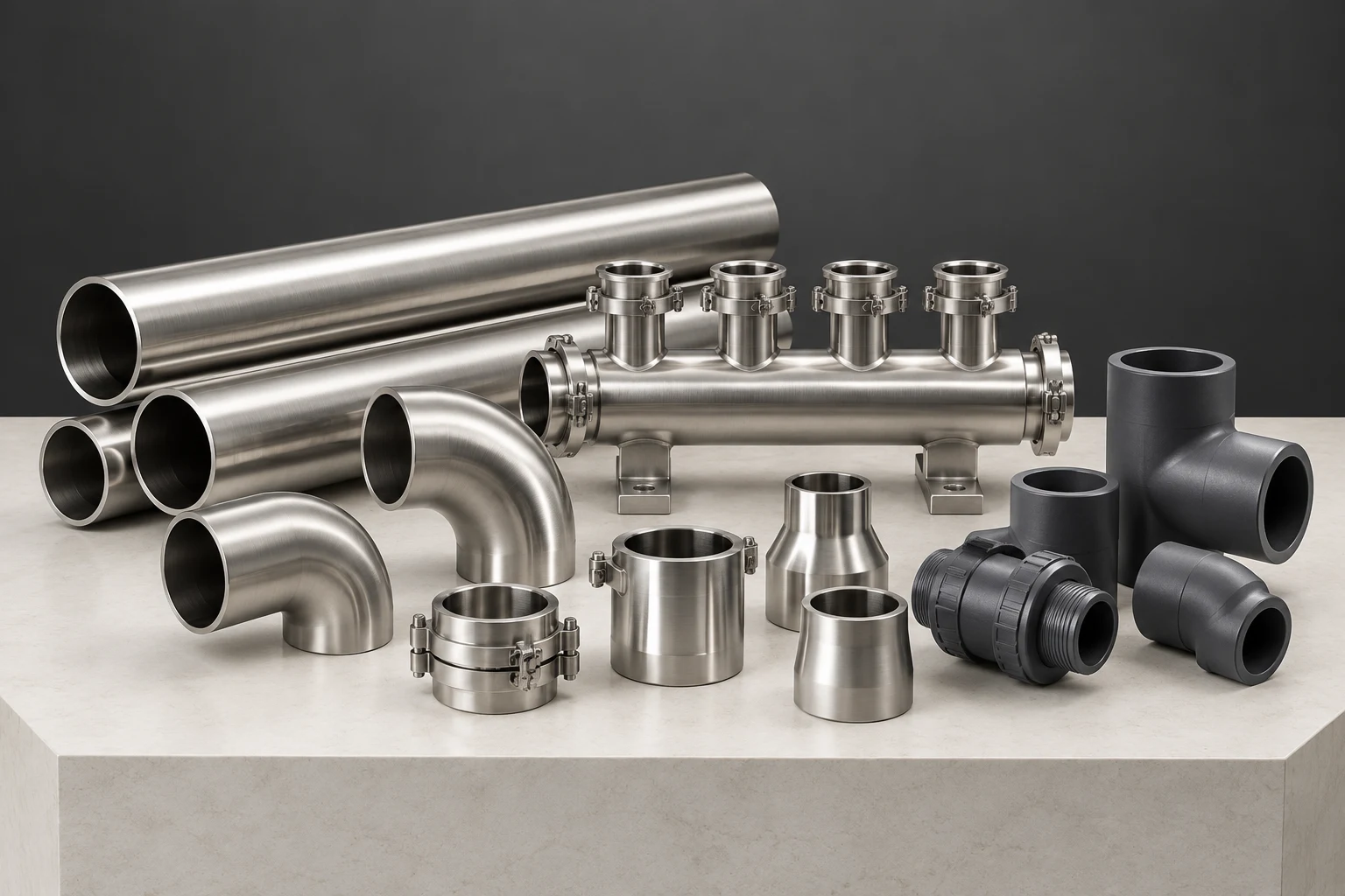
Design visualization
Develop around the application.
Connection Systems develops fittings, transitions, distribution manifolds, and the interfaces between pipe runs and equipment. Geometry and connection access follow the installation and service requirements.
Application
The intended use and installation or production interfaces define the product brief.
Specification
Materials, dimensions, acceptance criteria, and documentation follow the client’s requirements.
Delivery
Scope, supply arrangements, and integration are agreed during quotation.
Resolve the specification.
Material compatibility, joint details, isolation, replacement access, and the required test regime are specified with the pipe network. A reference size does not substitute for a confirmed service rating.
- Pipes & Connections
- Industrial and enterprise projects
- Client-defined integration
Size and specification.
Proposed design dimensions. Final equipment, performance, connections, and installation clearances are confirmed during specification and quotation.
| Specification | Compact reference | Standard reference | Large reference |
|---|---|---|---|
| Nominal selection | 20 mm | 50 mm | 100 mm |
| Basis | Proposed selection; actual service and connection dimensions specified separately | Proposed selection; service ratings defined in specification | Proposed selection; joint and installation details defined with the network |
Related programs.
Explore the design, the reference specification, and the configuration for each program.
Plumbing Networks
Connect the fixtures with the infrastructure serving them.
Scope: Fixtures, distribution, plant interfaces, and access
ClearFlow System
A connected drainage system designed to keep the flow moving.
Nominal system brief: 40 / 50 / 75 mm branches
Define what comes next.
Share the application, reference size, operating requirements, and destination. We develop the specification and quotation with your team.